PIC16 Управление LCD
PIC16 Управление LCD
Тук ще намерите асемблерен код и схеми за свързване на LCD дисплеи, базирани на контролера Hitachi HD44780U, с микроконтролери Microchip PIC16, използвайки само 3 I/O пина.
Дизайнът използва 74HC164 8-битов сериен към паралелен шифт регистър за минимизиране на използваните I/O пинове.
Необходими I/O пинове:
- Clock - За тактуване на шифт регистъра
- Data - За предаване на серийни данни
- LCD Enable - За управление на дисплея
Clock и Data пиновете могат да бъдат споделени с други периферни устройства, което прави това решение идеално за приложения с ограничен брой пинове.
Имплементацията е оптимизирана за минимален брой асемблерни инструкции с цел пестене на програмна памет, което е особено полезно за микроконтролери с ограничено пространство за инструкции.
Схеми
 Управление LCD с 74HC164 Схема
Изходен Код
;******************************************************************************
; LCD interface for Microchip PIC16 microcontrollers.
;
; author: Ivan Dachev
; email: [email protected]
; web: www.lz2gl.com
; version: v1.0
;
;******************************************************************************
;
; Program control 8-Bit Serial-Input/Parallel-Output Shift Register
; 74HC164 which is connected to LCD.
;
; It is implement to use only 3 ports from microcontroller:
; CLOCK - clock for 74HC164
; DATA - data for 74HC164
; STROBE - enable/disable for LCD read operation
;
; 14.01.2007 Initial Version
; All source here is small parts from my programs
; so to be usable for own use, change position
; of file registers to fit your program.
;
;******************************************************************************
;******************************************************************************
; Bit flags for SYNSTATUS
;
; Constants _XXX_BITS are used to make bit swapping
; example:
; movlw _LOCK_BITS
; xorwf SYNSTATUS, F
;
#define _INSTLCD SYNSTATUS, 5 ;5-bit Instruction/Data flag for LCD
#define _INSTLCD_BITS B'00100000'
;******************************************************************************
;
; Main preferences for program.
;
#define OUT2LCD_DELAY_TIME .62
;Delay counter for OUT2LCD_DATA.
;Each iteration is 3 instructions we must wait about 37000ns
;so (20Mhz - number is 62) (10Mhz - number is 31)
;******************************************************************************
;
; Defines IN/OUT for PORTA
;
#define OUT_LCDCLOCK PORTA, 1 ;Share CLOCK at RA1 for LCD
#define OUT_LCDDATA PORTA, 2 ;Share DATA at RA2 for LCD
#define OUT_LCDSTROBE PORTA, 3 ;Strob signal at RA3 for LCD
;******************************************************************************
; Define commands for LCD
;
#define LCD_CLEAR B'00000001' ; Clear display, home cursor
#define LCD_HOME B'00000010' ; Send cursor home
#define LCD_8BIT B'00111100' ; 8-bit interface, 2 display lines, 5x10 font
#define LCD_DISABLE B'00001000' ; Disable entire display
#define LCD_ENABLE B'00001100' ; Display enable, no cursor
#define LCD_MODESET B'00000110' ; Increment cursor, no scrolling
#define LCD_CURSOFF B'00001100' ; Cursor off
#define LCD_CURSON B'00001111' ; Cursor on and blink at position
#define LCD_CURSRIGHT B'00010100' ; move cursor right one space
#define LCD_SETADDR B'10000000' ; Set display address for writing
;******************************************************************************
; File registers
;
;general temp
tmp equ 0x50
;general counter
count equ 0x53
;used for delay functions
delay1 equ 0x5D
delay2 equ 0x5E
;other variables
SYNSTATUS equ 0x73 ;boolean flags
;******************************************************************************
;
; INITLCD
; -------
;
; Initializing LCD
;
; 03.07.2004 Changed according to HITACHI specification !
;******************************************************************************
;
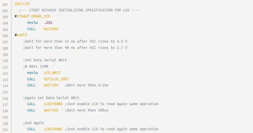
INITLCD
;--- START HITACHI INITIALIZING SPECIFICATION FOR LCD ----
#ifndef DEBUG_SIM
movlw .255
CALL WAITWMS
#endif
;Wait for more than 15 ms after VCC rises to 4.5 V
;Wait for more than 40 ms after VCC rises to 2.7 V
;Set Data Serial 8bit
;B 0011 1100
movlw LCD_8BIT
CALL OUT2LCD_INST
CALL WAIT5MS ;Wait more then 4.1ms
;Again set Data Serial 8bit
CALL LCDSTROBE ;Just enable LCD to read again same operation
CALL WAIT1MS ;Wait more then 100us
;And again
CALL LCDSTROBE ;Just enable LCD to read again same operation
;Set Data Serial 8bit, display 2 lines, Font to 5x10 dots
;B 0011 1100
movlw LCD_8BIT
CALL OUT2LCD_INST
;Turns display off / cursor off / blinck off
;B 0000 1000
movlw LCD_DISABLE
CALL OUT2LCD_INST
;Clears display and set address 0 of RAM
;B 0000 0001
movlw LCD_CLEAR
CALL OUT2LCD_INST
CALL WAIT2MS ;LCD_CLEAR need more wait to execute
;Set Cursor to move Increment / No shift
;B 0000 0110
movlw LCD_MODESET
CALL OUT2LCD_INST
;--- END HITACHI INITIALIZING SPECIFICATION FOR LCD ----
;Turns display on / cursor off / blinck off
;B 0000 1100
movlw LCD_ENABLE
GOTO OUT2LCD_INST
;RETURN goto will return ! same as return save place
;
; end ***********************************************************************
;
;******************************************************************************
;
; OUT2LCD_INST & OUT2LCD_DATA
; ---------------------------
;
; Output character or instruction in W to LCD
;
; For all OUT2LCD_DATA we must wait 37000ns
;
; For all OUT2LCD_INST expect below we must wait 37000ns
; for RETURN_TOHOME and CLEAR_DISPLAY we must wait 1,520,000ns
;
; Corrupts: count and tmp.
;******************************************************************************
;
OUT2LCD_INST
bsf _INSTLCD ;Change to instruction send
GOTO POUT2LCD
OUT2LCD_DATA
bcf _INSTLCD ;Change from instruction to data send
POUT2LCD
movwf tmp
movlw 008H
movwf count
NEXTOUT
bcf OUT_LCDCLOCK
GOTO $+1
bcf OUT_LCDDATA
rlf tmp,F
btfsc STATUS, C ;Check bit state skip if it is 0
bsf OUT_LCDDATA
GOTO $+1
bsf OUT_LCDCLOCK
decfsz count, F
GOTO NEXTOUT ;Go to send next bit
btfsc _INSTLCD ; OUT_LCDCLOCK is used for Instruction/Data switch
bcf OUT_LCDCLOCK
GOTO $+1
LCDSTROBE
;use this to repeat last operation again !
bsf OUT_LCDSTROBE ;enable LCD to read operation
GOTO $+1 ;wait LCD to do its job
bcf OUT_LCDSTROBE ;disable LCD to read operation
;--- from here LCD starts to execute operation ---
;--- so we need to wait it to finish him before next operation ---
movlw OUT2LCD_DELAY_TIME ;Wait for data and instructions
movwf delay1
decfsz delay1,F
GOTO $-1
RETURN
;
; end ***********************************************************************
;
;******************************************************************************
;
; Delay functions
;
; For 20Mhz
; 1 instruction - 200ns
; 1 call/goto instruction - 400ns
;
; For 10Mhz
; 1 instruction - 400ns
; 1 call/goto instruction - 800ns
;
; Here is formula to calculate each iterations call
;
; (767*(delay2-1) + 766)
; + 2 (call to WAITXXXLC)
; + 2 (init delay2)
; + 2 (goto delay2LOOP)
; + 2 final RETURN)
;
; 1ns = 10^-9s
; 1mcrs = 10^-6s
; 1ms = 10^-3s
;
; Names are for 20Mhz
;
; delay2 = 255 -> (iters 195592) (10Mhz 78,236,800ns) (20Mhz 39,118,400ns)
;
WAIT1MS
movlw .7 ;(iters 5376) (10Mhz 2,150,400ns) (20Mhz 1,075,200ns)
WAITWMS
movwf delay2
GOTO DELAY2LOOP
WAIT2MS
movlw .13 ;(iters 9978) (10Mhz 3,991,200ns) (20Mhz 1,995,600ns)
movwf delay2
GOTO DELAY2LOOP
WAIT5MS
movlw .33 ;(iters 25318) (10Mhz 10,127,200ns) (20Mhz 5,063,600ns)
movwf delay2
GOTO DELAY2LOOP
DELAY2LOOP ;(767*(delay2-1) + 766) iterations (without return)
#ifdef DEBUG_NODELAYS
RETURN ;USE ONLY FOR DEBUG
#endif
movlw .255
movwf delay1
DELAY1LOOP
decfsz delay1,F
GOTO DELAY1LOOP
decfsz delay2,F
GOTO DELAY2LOOP
RETURN
;
; end ***********************************************************************
;Технически Спецификации
Допълнителна Информация
Тази публикация е лицензирана под CC BY 4.0 от автора.