Antenna Tuning Device
This documentation details our custom antenna tuning unit (ATU) designed specifically for the V-Star Antenna. The tuner provides precise impedance matching across the entire HF spectrum (1-32MHz), optimizing power transfer and minimizing SWR for maximum antenna system efficiency.
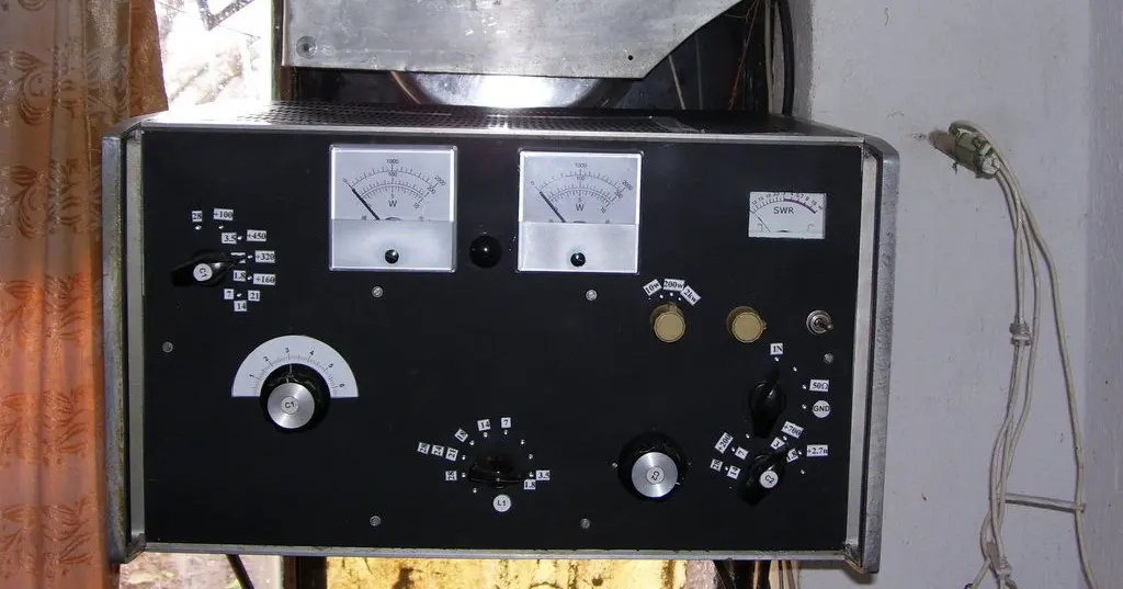
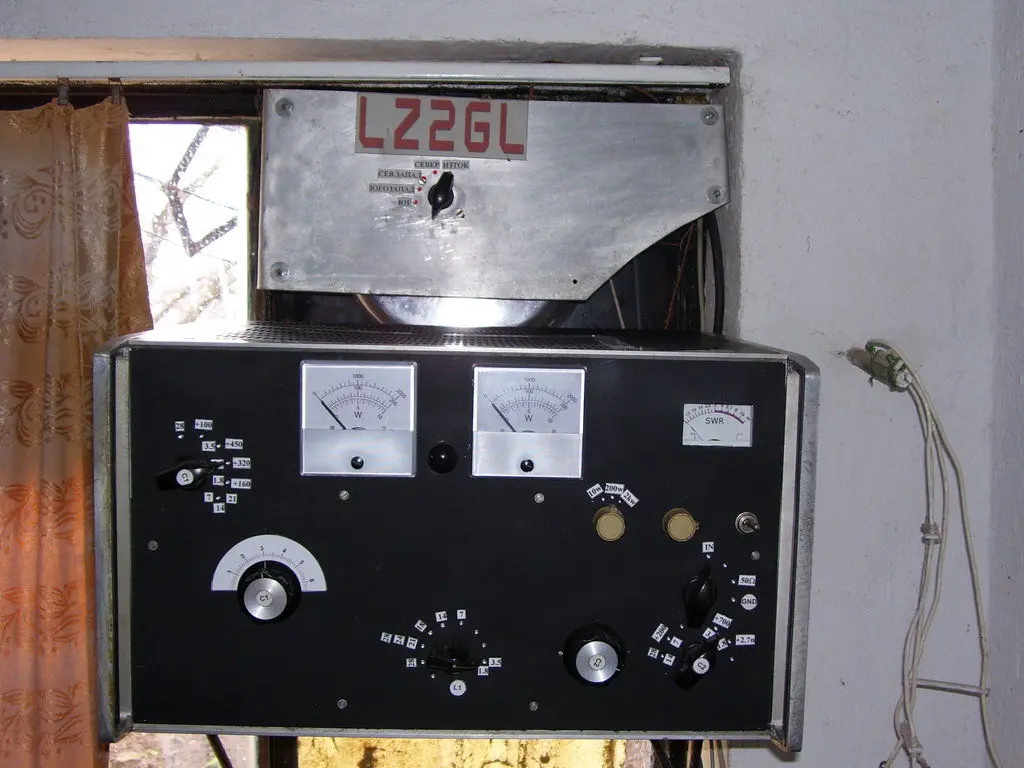
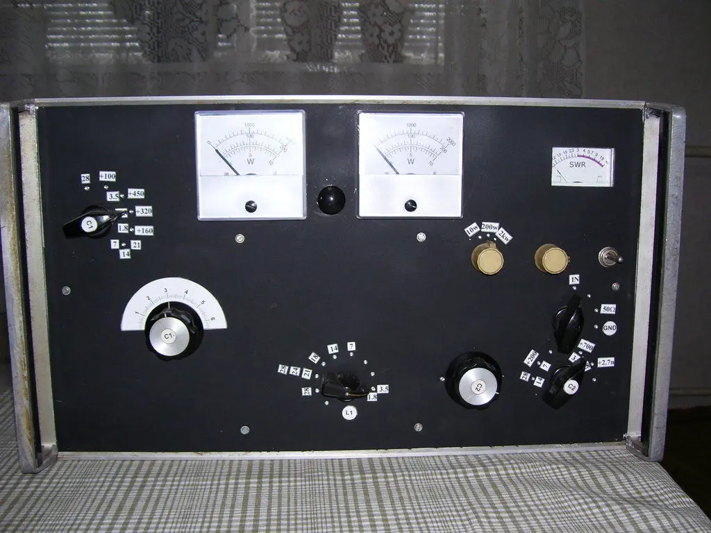
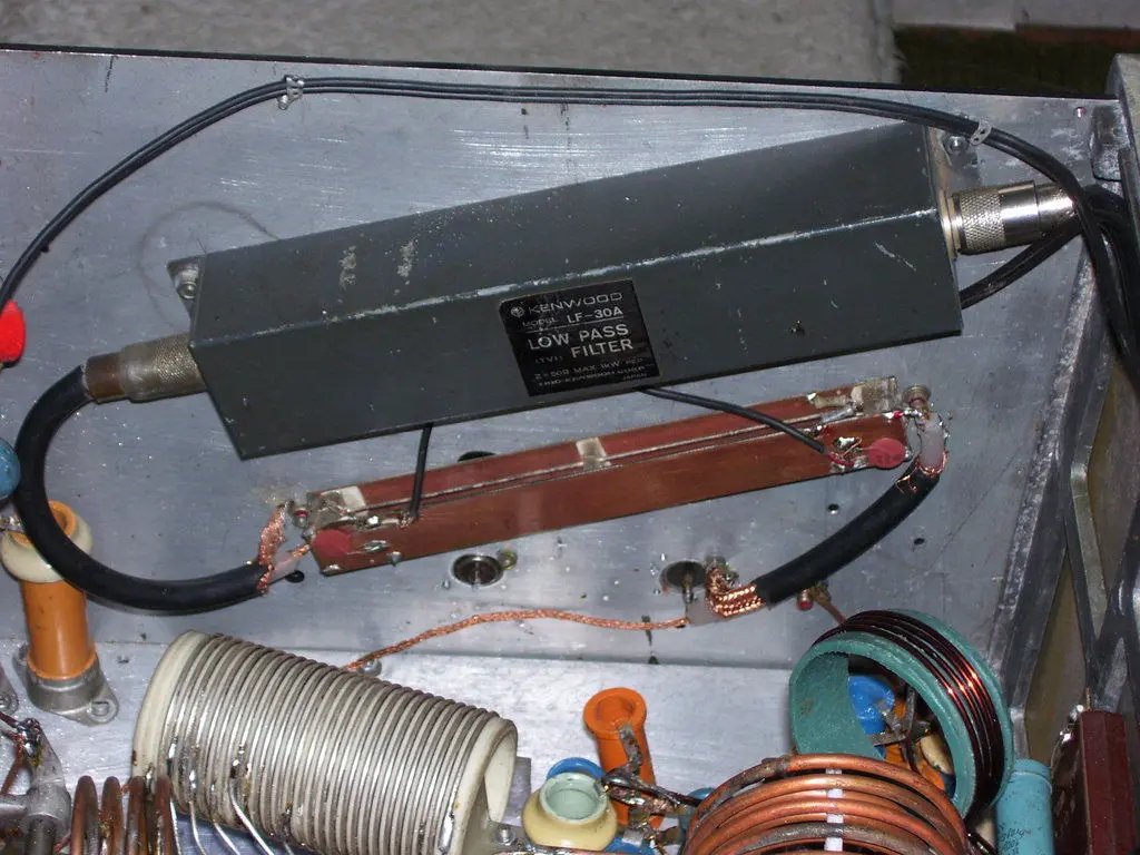
Gallery
Schematics
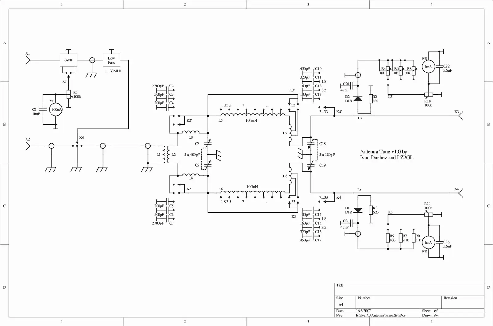 Antenna Tuning Unit Schematics
( as PDF) (1MHz-32MHz)
Description
We have extensively experimented with various antenna tuning solutions documented in literature and online resources. Our tests included symmetrical tuning devices for antennas with symmetrical lines, including T-match and L-match configurations at the output with baluns for symmetry, as well as standard LC networks with inductances. While all configurations were functional at 200W, the results fell short of our requirements.
The primary challenge with L-match and T-match devices using output baluns was significant power loss across different power levels (10W to 1kW). To handle 1kW efficiently without balun radiation, the components needed to be substantially oversized. However, when operating at 10W with a 1kW-rated balun into a 600Ω symmetrical load, the output power dropped to merely 1.5W. This necessitates separate tuning devices for low and high power operations.
Our experiments with standard LC-type matching networks achieved efficiency above 90% but presented several challenges:
- The output components, particularly capacitors, must be significantly oversized to handle voltages approaching 3000V.
- Minor tuning errors can be catastrophic for both the tuner and the final amplifier stage.
- The bandwidth is extremely narrow at lower frequencies, requiring constant adjustment (every 5kHz at 1.8MHz, every 30kHz at 3.5MHz).
- At certain resonant points, the tuner amplifies harmonics, leading to television interference regardless of final amplifier design quality.
Given our antenna’s proximity to neighboring properties and CATV infrastructure, television interference was unacceptable both professionally and ethically. This led us to implement a low-pass Collins filter design, previously only theoretical for antenna applications. After extensive testing, we developed a configuration operating from 1.5MHz to 32MHz with significantly improved tuning characteristics. The bandwidth improved substantially: 25kHz at 1.8MHz and 100kHz at 3.5MHz. Crucially, it provided superior harmonic suppression, eliminating TV interference even at 1kW operation.
While extensive theoretical documentation exists in technical literature, we’ll focus on practical implementation. The Collins filter functions as a low-pass filter, passing only the operating frequency while attenuating higher frequencies. Specifically, the dual Collins filter configuration optimally matches the final stage to the antenna. Our implementation achieves approximately 98% efficiency, making it suitable for both QRP (1W) and high-power (1kW) operations.
This design represents years of practical experimentation. Following our specifications precisely will ensure successful replication and avoid the complications we encountered with previous tuning solutions.
Notes to Scheme
Inductors L3 and L4 serve as compensation coils, utilized exclusively for 1.8MHz and 3.5MHz bands to increase the input transformer’s inductance. These inductors can be air-wound or constructed using PVC forms. For 1.8MHz and 3.5MHz band operation, we utilize the combined inductance of L5 and L6. The tuner’s efficiency varies by frequency: 93% at 1.8MHz, 95% at 3.5MHz, and 98% across the 7MHz to 32MHz range. These measurements were taken with 1W input power at 50Ω, with efficiency calculated as the percentage of power delivered to a 600Ω load.
| L1 | 5 – turns of copper pipe \(\phi\,4\,mm\) L1 is within L2 |  |
| L2 | 5 – turns of copper pipe \(\phi\,4\,mm\) L1 is within L2 |  |
| L3 & L4 | 4 – turns of copper wire \(\phi\,2\,mm\) PVC body \(\phi\,62\,mm\) |  |
| L5 & L5 | 27 – turns of copper wire \(\phi\,2\,mm\) ceramic body \(\phi\,52\,mm\) outlets of these turns: 2nd, 4th, 6th, 8th and 13th |  |
| L7 & L8 | 4 – turns of copper wire \(\phi\,4\,mm\) ceramic body \(\phi\,52\,mm\) outlets at 1st and 2nd turn |  |
The following diagram illustrates the dimensions of transmission line Lx, which is used for both indicator circuits to monitor the tuner’s output signal.