Frequency and LC Meters
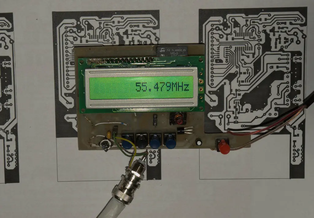
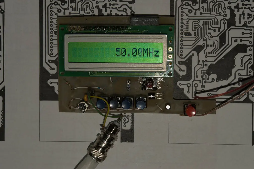
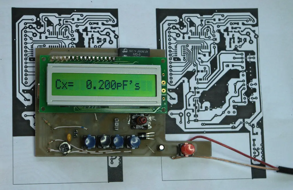
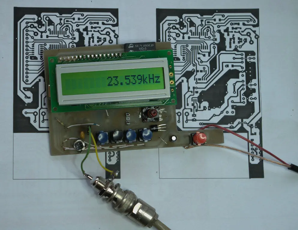
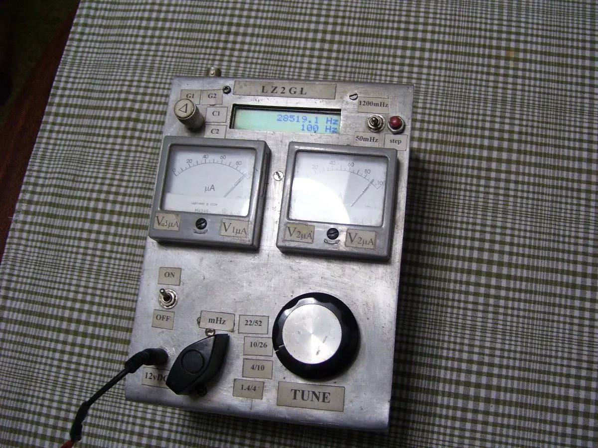
Here we have put the diagrams of our devices for measuring frequency, inductance and capacitance.
- Frequency meter v3.1 (2003 – 2007)
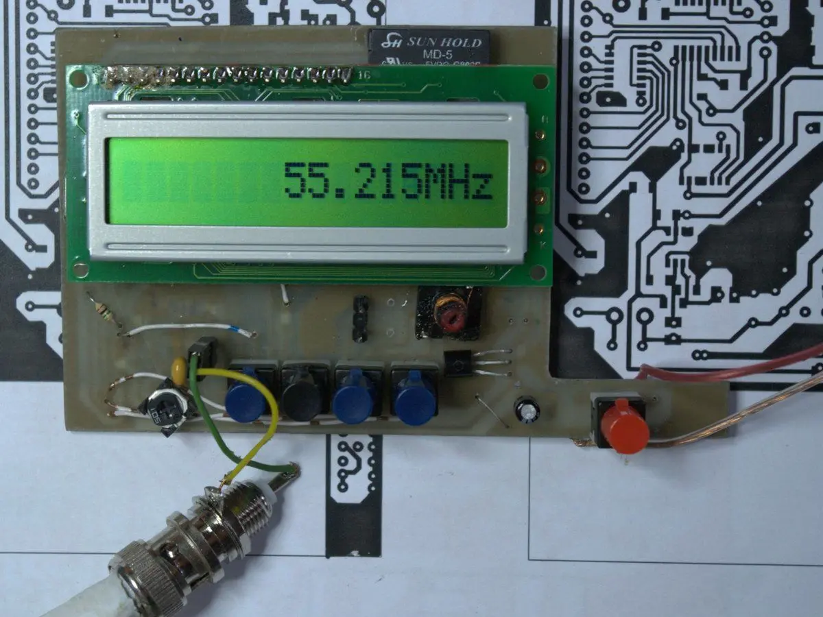
- 1Hz – 1000MHz
- Frequency meter with functions v2.4 (2004 – 2005)
- F1: 1Hz – 1000MHz
- F2: 1Hz – 50MHz
- F3: 1Hz – 50MHz
- Frequency and LC meter v1.2 (2005 – 2008)
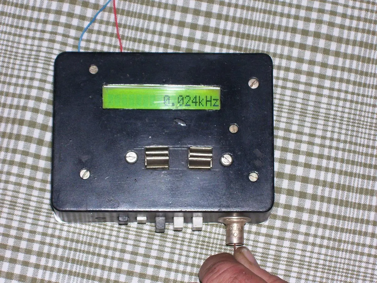
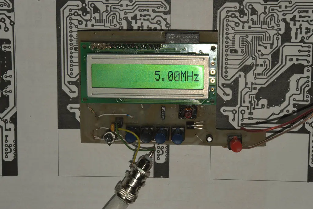
- 1Hz – 60MHz
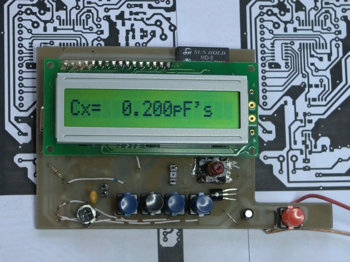
- 0.01pF – 150nF
- 150nF – 1uF
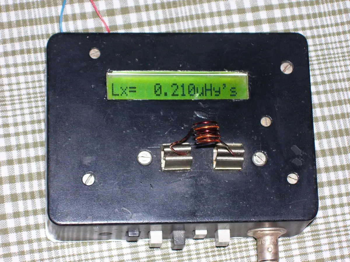
- 0.001uH – 100mH
If you have an interest in any of the measuring instruments, we can produce one for your own use. For a price quote and device manufacturing time information, please contact us: LZ2GL
Frequency Meter Gallery
L/C Meter Gallery
Other Meters Gallery
Datasheets
Schematics
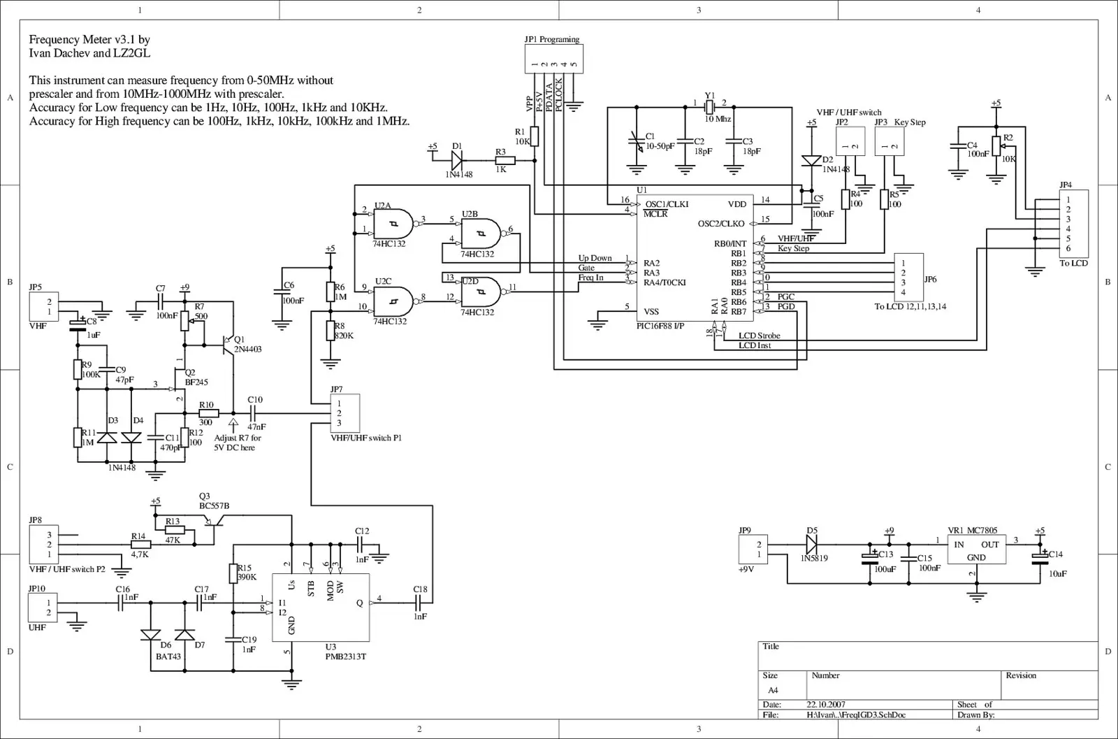 Frequency meter v3.1
( as PDF)
(1Hz-50MHz) and (10MHz-1100MHz)
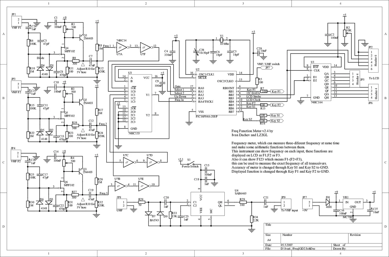 Frequency function meter v2.4
( as PDF)
F1 (1Hz-1000MHz), F2 (1Hz-50MHz) and F3(1Hz-50MHz)
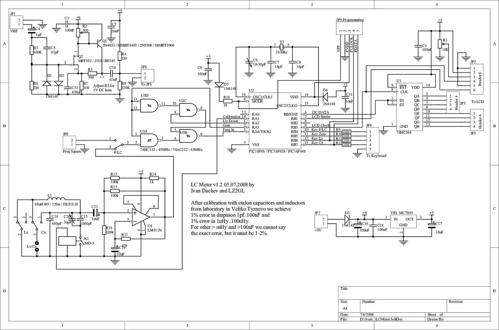 Frequency (1Hz-50MHz) and LC meter v1.2
( as PDF)
(1Hz-60MHz), (0.01pF – 150nF), (150nF – 1uF) and (0.001uHy-100mHy)
Description
We first developed a frequency meter using the PIC16F84A microcontroller in 2003, based on various online schematics. We wrote the program using documentation from Microchip and other resources found online. The device was completed in early 2003, with the first version launched by the end of March. It performed measurements accurately, although there were some software bugs.
In 2004, we conceived an improved version of the frequency meter-essentially a new device capable of measuring three frequencies simultaneously and performing arithmetic calculations between them. One crucial calculation was F1 – (F2 + F3), where F1 represents the radio synthesizer frequency, F2 the first intermediate frequency, and F3 the second intermediate frequency. This device enabled precise measurement of amateur radio transceiver transmission frequencies with single or double conversion.
In 2005, after brief research and leveraging our experience with the new transceiver and its programming, we enhanced the software for both frequency meter variants. We improved the code and key reading functionality while fixing a minor error in the main timing cycle. This error had caused an anomaly: at 10 Hz precision, readings like 10.000.01 Hz showed the last digit fluctuating between 0 and 1, which was normal. However, at higher steps like 10 kHz, readings like 10.02 kHz showed the last digit fluctuating between 1-2 instead of 0-1. We discovered we had overlooked one instruction in the timing cycle-a combination of half an instruction each for opening and closing the Frequency Gate. Our main timing cycle uses four levels of nesting, providing an optimal combination of cycles and time selection options for various frequency meter factors of 64 or 256. This allows the device to measure frequencies from 1000-1500 MHz.
We then decided to develop an LC meter, which required a microcontroller to measure LC generator frequency and perform complex calculations. Generator formulas and schematics are widely available online, with L/C Meter IIB by Neil Heckt being a notable reference.
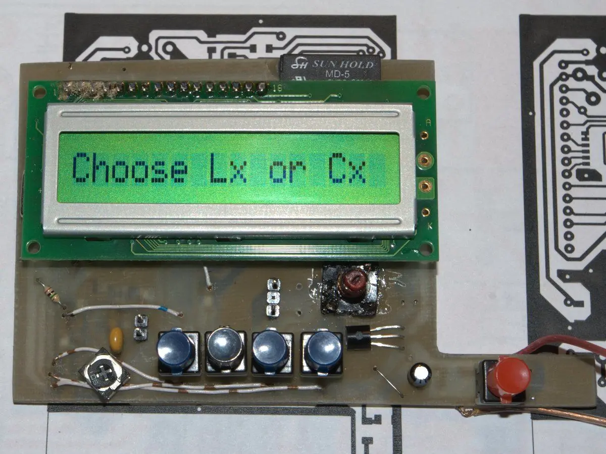
We developed the program ourselves, incorporating the necessary frequency meter calculations. The implementation required floating-point operations using Microchip AN575, which significantly increased the code size, reaching the 1KB code page limit of the PIC16F84. Consequently, we switched to the PIC16F88 (PIC16F628/648), which maintained pin compatibility for core functions while providing sufficient memory.
While the device could potentially be built with a PIC16F84 by removing the frequency meter function to reduce code size and retaining only LC measurement capabilities, we discovered that the older processor was actually more expensive than the newer PIC16F88. This price disparity arose because Microchip’s newer manufacturing technology reduced production costs, while demand for the older model drove up its price. Therefore, it made more sense to use the newer models, which offered more features, memory, and improved frequency measurement sensitivity.
After development, the device was calibrated using standard inductance and capacitance equipment at a laboratory in Veliko Tarnovo. The calibration achieved approximately 1% error for ranges of 1pF-100nF and 1µH-1mH, while other ranges, though not precisely measured, were estimated to have 1-2% error.
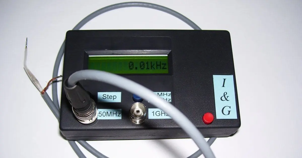
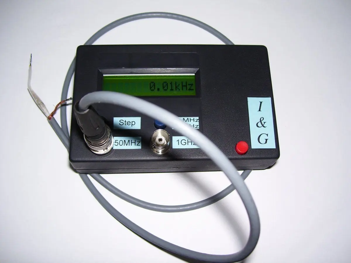
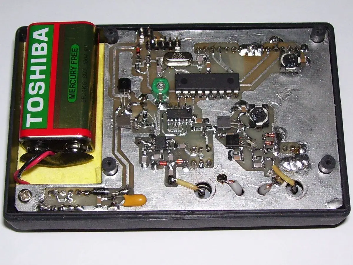
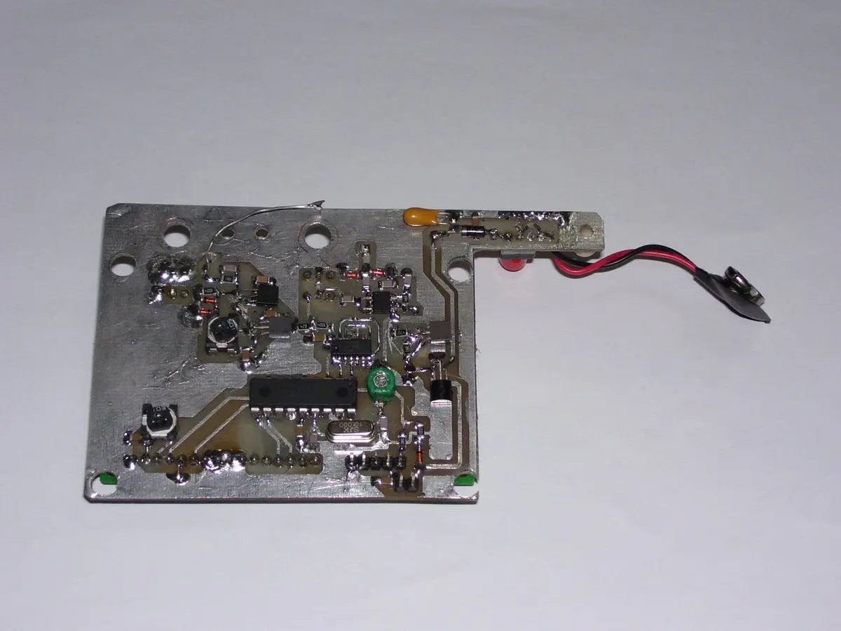
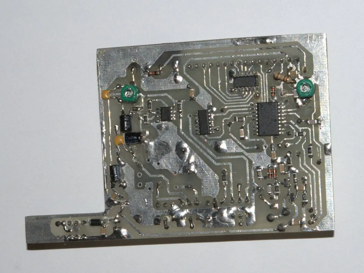
In 2007, we upgraded the frequency meter to version 3.1. We eliminated the 74HC164 to reduce power consumption and implemented a 4-bit interface for the LCD. We also modified the current divider and began using PMB2313T for high-frequency input. This divider, in SMD format, provides excellent performance in the 50MHz-1.1GHz range. We redesigned the PCB to fit a smaller enclosure and adopted SMD format for most components.
In 2008, we upgraded the LC meter to version 1.2. We similarly redesigned this device’s PCB for a smaller enclosure and converted most components to SMD format. As an additional feature, we tested the 74AC132, achieving excellent maximum measurement frequency capabilities of up to 60MHz without a high-frequency divider.
